
INFINITE SYSTEMS INSIGHTS:
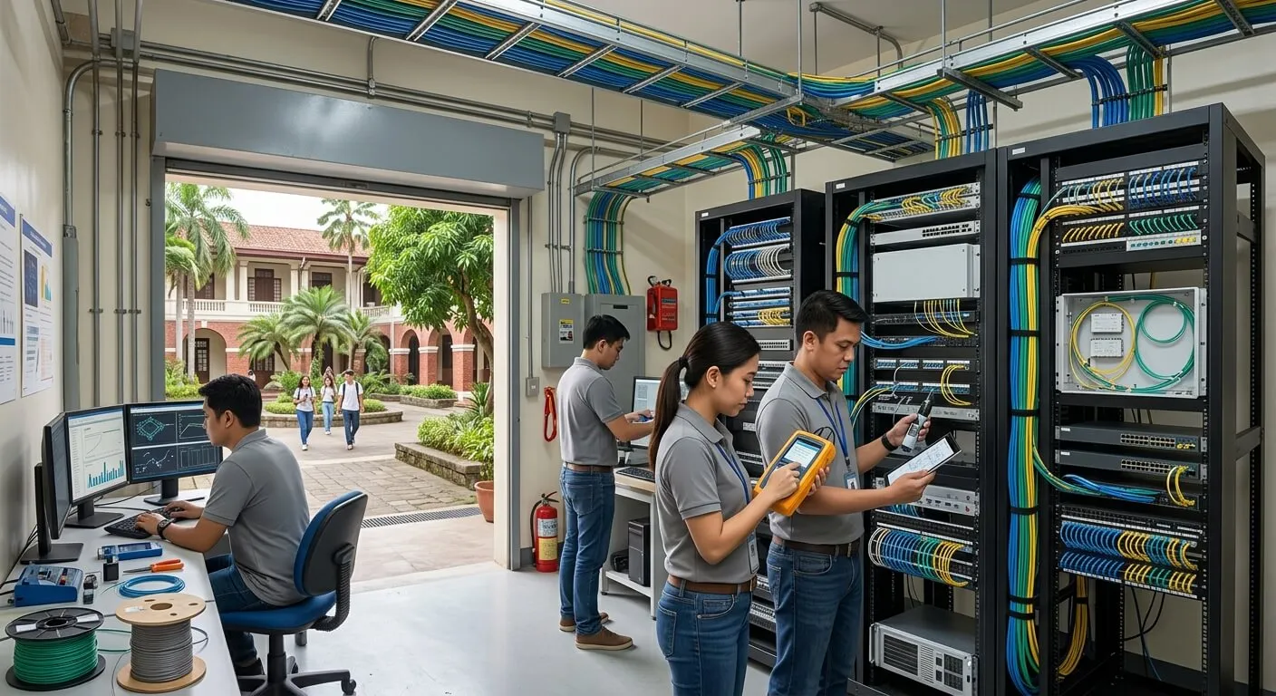
Structured cabling testing in the Philippines should do more than confirm that cables are connected. It should verify that installed copper and fiber links meet the project’s specified performance requirements, can be traced to their physical locations, and are supported by complete records for acceptance, operation and future maintenance.
Quick Takeaway
A professional cabling acceptance process should connect physical inspection, instrument testing, fault correction, labeling and final documentation. Continuity checks alone are not equivalent to cable certification, and fiber testing should follow the specific requirements of the installed system and project specification.
Testing Turns Installation Into Verifiable Infrastructure
A neat telecommunications rack does not automatically prove that a structured cabling installation will perform reliably. Acceptance testing provides measurable evidence that installed permanent links or channels comply with the project’s specified cable category, fiber performance requirements and documentation standards.
For commercial buildings, schools, offices, industrial facilities, data rooms and other Philippine projects, testing should be planned as part of the installation and commissioning process rather than treated as a final paperwork exercise.
Verify the Link
Confirm that copper and fiber links meet the specified performance limits for the intended network application.
Identify Every Link
Connect each test result to the rack, patch-panel port, outlet, cable ID or fiber strand it represents.
Document the Result
Provide organized reports and records that support project turnover, troubleshooting and future maintenance.
A Practical Structured Cabling Testing Workflow
Testing is more effective when the required scope and documentation format are defined before the final installation stage. A typical workflow can be organized into five steps:
TESTING WORKFLOW
1. Define the test scope — Confirm cable category, link type, fiber type, applicable limits, test configuration and required deliverables.
2. Verify the physical installation — Check routing, labeling, termination, bend radius, pathways, patch panels and outlet locations.
3. Perform instrument testing — Test copper and fiber using appropriate instruments and the specified reference procedures.
4. Investigate and correct failures — Identify the physical, termination or configuration issue, make the correction and retest the affected link.
5. Compile acceptance records — Match results to cable IDs, rack locations, outlets, ports and fiber strands.
Copper Certification for Cat6 and Cat6A
For Cat6 and Cat6A structured cabling projects, the testing scope should clearly identify whether the requirement is for a permanent link or a channel and which standard or project-specific performance limits apply.
Certification instruments evaluate multiple electrical characteristics of the installed link. This provides substantially more information than a basic continuity check and helps demonstrate whether the completed cabling is suitable for its intended network application.
Important: The required test configuration should match the project’s acceptance criteria. A permanent-link test and a channel test are not interchangeable simply because they use the same installed cable.
Wiremap Is Necessary but Not Sufficient
Wiremap testing can identify conditions such as opens, shorts, reversals, crossed pairs and split pairs. However, a correct wiremap does not by itself demonstrate that a high-speed copper link meets all required transmission-performance limits.
Where project acceptance requires certification, the appropriate certification test should be performed using a suitable calibrated instrument and the specified test configuration.
Fiber Insertion Loss Testing
Optical loss testing verifies end-to-end attenuation across a fiber link at the wavelengths specified for the project. Proper reference procedures, test equipment and launch conditions are important because the measurement should represent the installed link rather than an inconsistent test setup.
Connector cleanliness matters. Dust, oil and other contamination can increase measured optical loss and may damage mating interfaces. Fiber connectors should therefore be inspected and cleaned using appropriate procedures before testing.
When OTDR Testing Is Useful
An Optical Time-Domain Reflectometer (OTDR) can provide information about fiber length, event locations, splice characteristics and reflective faults. This can be particularly useful when troubleshooting unexpected loss or locating an event along an installed fiber route.
OTDR testing and end-to-end insertion-loss testing provide different information. An OTDR should therefore complement, rather than automatically replace, loss testing when the project specification requires both.
Insertion-Loss Testing
Measures end-to-end optical attenuation across the installed link using the specified reference procedure.
OTDR Testing
Helps locate events, estimate fiber length and investigate reflective or localized conditions along the route.
Labeling and Test Traceability
Test results become more useful when every result can be traced to the actual installed link. Test IDs should correspond with rack numbers, patch-panel ports, outlet identifiers and fiber strand assignments.
For example, a test result identified only as “Pass” provides limited operational value if the project team cannot determine which rack, patch-panel port or outlet it represents. Consistent naming and labeling connect the electronic test record to the physical infrastructure.
A traceable test record should answer:
- Which rack or telecommunications room?
- Which patch-panel port?
- Which outlet or endpoint?
- Which cable or fiber strand?
- Which test result and corrective action, if applicable?
Common Causes of Failed Test Results
A failed result should be investigated rather than simply removed from the final documentation. Common causes can include:
Once the cause has been identified, the link should be repaired and retested. Final documentation should accurately reflect the completed and retested installation rather than changing or concealing failed measurements.
Building a Complete Cabling Acceptance Package
A structured cabling acceptance package should provide enough information for the owner, consultant, contractor and future maintenance team to understand what was installed and how it was tested.
Typical project records include:
- Final copper certification reports
- Fiber insertion-loss test results
- OTDR traces where required
- Cable and port schedules
- Rack, patch-panel and outlet labels
- Fiber strand assignments
- As-built pathways and cable-routing records
- Documentation of corrected and retested failures
Testing Should Be Planned Before Installation Is Complete
Testing requirements should be established during project planning so installers understand the required cable category, link configuration, labeling convention, test limits and documentation format before installation begins.
This approach can reduce turnover delays because failed links, missing labels and incomplete records can be addressed before final acceptance rather than discovered after the network is already in operation.
PROJECT CHECKLIST
Define — Cable category, fiber type, link type, test limits and applicable project requirements.
Coordinate — Labeling, rack schedules, patch-panel assignments, pathways and access to installed infrastructure.
Test — Perform the required copper and fiber measurements using suitable instruments and procedures.
Turn Over — Deliver traceable test reports, corrected results, schedules and as-built documentation.
Frequently Asked Questions
Is a continuity tester enough for Cat6?
No. Continuity testing confirms basic conductor mapping but does not certify the complete performance of a Cat6 link against the applicable transmission requirements.
What is cable certification?
Cable certification is instrument-based testing of an installed link against defined performance limits. It provides documented results that can be used for project acceptance and troubleshooting.
Does fiber always need OTDR testing?
Not necessarily. Testing requirements depend on the project specification and fiber system. Insertion-loss testing and OTDR testing provide different types of information and may both be required.
Why do fiber connectors need cleaning before testing?
Contamination can increase optical loss and potentially damage fiber interfaces. Cleaning and inspection help establish more reliable test conditions.
Should failed links stay in the final report?
Project records should accurately document testing and corrective work. The acceptance package should clearly identify the final corrected and retested results while retaining appropriate records of failures and remediation.
Why is labeling important?
Labeling connects test results to the actual rack, patch-panel port, outlet or fiber strand. This makes the infrastructure easier to operate, troubleshoot, maintain and expand.
RELATED INFINITE SYSTEMS SOLUTIONS
Structured Cabling Systems
CCTV and Video Surveillance Systems
STRUCTURED CABLING TESTING PHILIPPINES
Need Cabling Testing or Project Acceptance Support?
Infinite Systems can help assess installed copper and fiber infrastructure, define the appropriate testing scope, identify documentation requirements and prepare traceable acceptance records for structured cabling projects.