
INFINITE SYSTEMS INSIGHTS
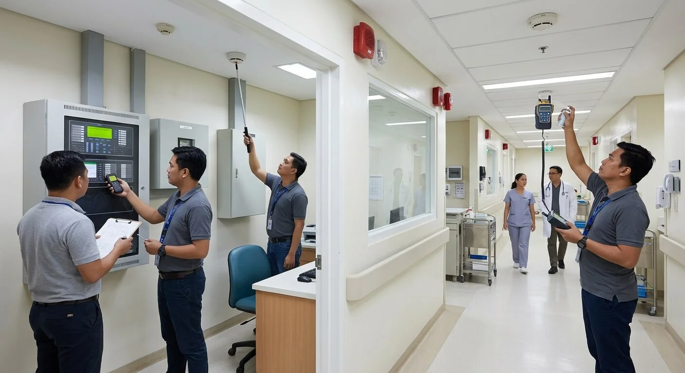
Discover and understand fire alarm commissioning in the Philippines, including device testing, notification appliances, cause-and-effect verification, system interfaces, batteries, records, punch lists and final turnover.
PLANNING PRINCIPLE
A fire alarm panel showing normal status does not prove that the complete life-safety sequence works as intended.
Commissioning should verify field devices, notification, interfaces, power, programming and documented cause-and-effect behavior against the approved project requirements.
01 / PREPARE
Confirm Readiness
Review approved drawings, device schedules, programming and interface availability before functional testing.
02 / TEST
Verify Field Devices
Test initiating devices, notification appliances, points and panel indications using appropriate procedures.
03 / INTEGRATE
Verify Cause & Effect
Confirm that alarm conditions produce the required building responses and interface outputs.
04 / TURN OVER
Document & Close
Resolve punch-list items, complete retesting and organize final records, training and turnover documentation.
01 / PROJECT CONTEXT
Commissioning Is More Than Device Activation
Fire alarm commissioning is not simply the process of activating detectors and checking whether the panel displays a normal condition. The installed system needs to be evaluated as an operating life-safety system, including field devices, notification, programming, power supplies and interfaces.
The objective is to confirm that the installed system performs the required response for defined alarm, supervisory and fault conditions and that the final installation corresponds with the approved project requirements.
ENGINEERING NOTE
A successful panel check does not automatically confirm the operation of downstream building systems. Where interfaces are part of the approved design, they should be included in coordinated functional testing.
02 / PRE-COMMISSIONING
Confirm Pre-Commissioning Readiness
Full functional testing is more effective when the installation is sufficiently complete and the information required for testing is available. Before starting, confirm the approved drawings, device schedules, addressing, circuit completion, panel programming and interface availability.
Approved Information
Drawings, device schedules and cause-and-effect documentation should be available for reference.
Installation Status
Field devices, circuits and associated equipment should be sufficiently complete for the planned tests.
Programming
Confirm addressing, labels, programmed outputs and required logic before functional testing.
Interfaces
Confirm that relevant connected systems and responsible trades are ready for coordinated testing.
Unfinished construction, unavailable interfaces or temporary programming can invalidate or limit the results of a commissioning test. These conditions should be recorded rather than treated as completed testing.
03 / INITIATING DEVICES
Test Smoke Detectors, Heat Detectors and Manual Call Points
Initiating devices should be tested using appropriate methods for the installed equipment. The test should verify not only that an alarm condition is generated, but also that the correct point, location and event appear at the fire alarm control panel and applicable annunciators.
FIELD VERIFICATION
- Verify device identification and location.
- Confirm the correct point appears at the panel.
- Check applicable annunciator indications.
- Confirm the programmed alarm response.
- Record devices that fail or require correction.
Other initiating devices should be tested according to the equipment and project scope. Testing methods should be appropriate for the installed device and carried out using safe, approved procedures.
04 / NOTIFICATION
Verify Notification Appliances by Area or Zone
Fire alarm notification should be tested according to the approved system design. Audible and visual notification appliances should operate in the intended areas or zones and respond correctly to the programmed alarm condition.
Audible Notification
Verify the applicable audible devices and programmed notification zones.
Visual Notification
Where applicable, confirm visual notification operates in the intended areas.
Output Programming
Confirm circuits, modules and programmed outputs respond to the required alarm conditions.
IMPORTANT
Notification testing should be coordinated with building occupants, site operations and other affected trades where required. The exact test procedure should follow the approved project requirements and applicable procedures.
05 / CAUSE & EFFECT
Verify the Approved Cause-and-Effect Matrix
The cause-and-effect matrix defines what should happen when a particular alarm, supervisory or other defined condition occurs. Commissioning should use the approved matrix as the reference for functional testing.
Input
Identify the initiating or supervisory condition being tested.
Logic
Confirm the programmed system response corresponds to the approved sequence.
Output
Verify notification and applicable control outputs.
Building Response
Confirm the connected building system performs the intended response where applicable.
Depending on the project design, interfaces may include door release, selected elevator functions, smoke-control systems, emergency audio or monitoring outputs. The actual interface scope should be determined from the approved project documents rather than assumed to be universal.
ENGINEERING NOTE
The existence of an interface does not by itself prove that the required sequence works. Each applicable interface should be functionally tested with the responsible trade.
06 / POWER & FAULT CONDITIONS
Verify Primary Power, Batteries and Fault Indications
Commissioning should include verification of the fire alarm system’s primary and standby power arrangements. Battery condition, applicable power-transfer behavior and required trouble indications should be checked against the installed system and project requirements.
Primary Power
Confirm normal operating power and applicable indications.
Standby Power
Verify battery and standby power behavior according to the system requirements.
Fault Indications
Confirm selected fault and supervisory conditions generate the required indications.
SAFETY NOTE
Fault simulations and power-related tests should only be performed through safe, approved procedures appropriate to the installed system and project testing requirements.
07 / INTEGRATED SYSTEMS TESTING
Coordinate Fire Alarm Interfaces With Other Building Systems
Modern commercial projects may connect the fire alarm system with other building systems. When those systems participate in the approved fire response, integrated testing should involve the responsible trades and system representatives.
Access Control
Verify applicable emergency door behavior where included in the approved sequence.
Elevators
Test applicable fire-response functions where included in the project design.
Mechanical / Smoke Control
Coordinate applicable equipment responses and interface signals.
BMS / Emergency Audio
Verify applicable monitoring, control or notification interfaces.
Integrated testing should identify the initiating condition, expected response, responsible trade and actual test result. Any interface that cannot be tested should be clearly recorded as incomplete rather than assumed to have passed.
08 / PUNCH LIST
Document Failures, Corrections and Retesting
Commissioning commonly identifies devices, programming items or interfaces that require correction. These should be recorded in a controlled punch list so that the project team can distinguish completed tests from outstanding work.
PUNCH-LIST RECORD SHOULD IDENTIFY:
- Device or interface involved
- Location or system reference
- Observed condition
- Required correction
- Responsible party where applicable
- Retest date or status
- Final test result
Corrected items should be retested. A revised programming file or physical correction does not by itself establish that the final system behavior has been successfully verified.
09 / TURNOVER
Fire Alarm Turnover and Final Documentation
Turnover should provide the owner or responsible operator with the information needed to understand, operate and maintain the completed system. The exact documentation package depends on the project requirements and agreed scope.
As-Built Records
Provide the agreed final drawings and installed device information.
Test Records
Maintain commissioning and retest results for the completed scope.
Programming
Provide programming backups where applicable and included in the project scope.
Training
Train designated personnel on applicable operation and response procedures.
10 / COMMISSIONING WORKFLOW
A Practical Fire Alarm Commissioning Workflow
01 — Review
Review approved drawings, device schedules and cause-and-effect requirements.
02 — Prepare
Confirm installation readiness, programming and interface availability.
03 — Test
Test initiating devices, notification, power and applicable fault conditions.
04 — Integrate
Coordinate functional testing with affected building systems and trades.
05 — Correct
Record punch-list items, implement corrections and perform required retests.
06 — Turn Over
Complete documentation, training and agreed turnover requirements.
11 / COMMISSIONING CHECKLIST
Fire Alarm Commissioning Checklist
- Approved drawings and device schedules available
- Approved cause-and-effect matrix available
- Device addresses and locations verified
- Initiating devices tested
- Notification appliances tested
- Panel and annunciator indications verified
- Primary and standby power checked
- Battery condition and applicable indications verified
- Selected fault and supervisory conditions tested
- Applicable access-control interfaces tested
- Applicable elevator interfaces tested
- Applicable mechanical or smoke-control interfaces tested
- Applicable BMS or emergency-audio interfaces tested
- Failed items documented in a punch list
- Corrected items retested
- As-built records and device information completed
- Programming backups provided where applicable
- Training and turnover records completed
12 / RELATED SOLUTIONS
Related Infinite Systems Solutions
Fire Alarm & Life Safety Systems
Preventive Maintenance Services
13 / FREQUENTLY ASKED QUESTIONS
Frequently Asked Questions
Is fire alarm commissioning the same as preventive maintenance?
No. Commissioning verifies a new or modified installation before turnover, while maintenance supports continued operation after acceptance.
What is a cause-and-effect matrix?
It documents which outputs and building responses should occur for defined alarm, supervisory or other specified inputs.
Should access-controlled doors be tested?
Yes, where their emergency behavior is part of the approved fire response and interface scope.
Who should attend integrated testing?
Relevant fire alarm, electrical, access-control, elevator, mechanical, BMS, emergency-audio or other responsible trades should participate when their systems are affected.
What documents should be turned over?
Typically the agreed as-built drawings, device information, test records, programming backups where applicable, manuals and training records.
Does commissioning replace authority inspection?
No. Project commissioning does not replace approvals, inspections or other requirements applicable to the project and its authority having jurisdiction.
PLAN YOUR PROJECT
Need a Site-Specific Fire Alarm Assessment?
Infinite Systems can assess the project, review the installed fire alarm scope, coordinate applicable interface testing and develop a practical commissioning or corrective-work scope.